Keyless Entry Install
1995 W124 E-Class
by Benzmac
2/13/01
Note - This procedure assumes you are installing a REC-8 keyless module. Other keyless systems may or may not be similar.
STEP-1
Move both front seats fully forward
Remove back seat by pushing on red tabs while lifting seat front. Pull rear seat out toward front seats.
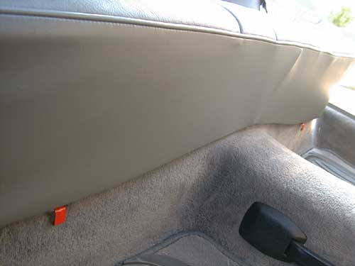
STEP-2
Pull up the carpet pad on the left side of the car to gain access to the Convenience Control Module.
Pull up the carpet on the right side of the car to gain access to the vacuum pump which is enclosed in a rubber foam case.
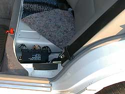
STEP-3
Remove the vacuum pump from the foam enclosure by first sliding the foam enclosure rearward until it is free. Open the enclosure and slide away from pump.
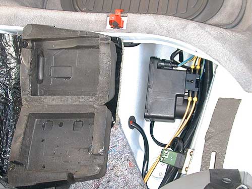
STEP-4
Pry up on the retaining clip that holds the vacuum supply lines to free vacuum line connector from the pump. This will give you easier access to the pump since there is very little slack in the vacuum lines. Be very careful not to break this clip.
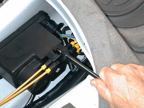
STEP-5
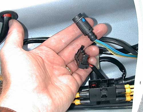
Unplug the round and rectangular plugs from the pump.
STEP-6
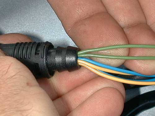
Find the 2 green wires on the round connector. You will have to cut one of these wires. Usually the correct wire is a little looser in the wire harness. Try gently pulling each wire individually from the wire harness which is to the right of this photo (do not pull from the plug). You have a 50/50 chance of cutting the right wire!
Pick a green wire and cut it. Be careful not to ground the cut green wire or you will blow a fuse. The fuse box is under the hood.
STEP-7
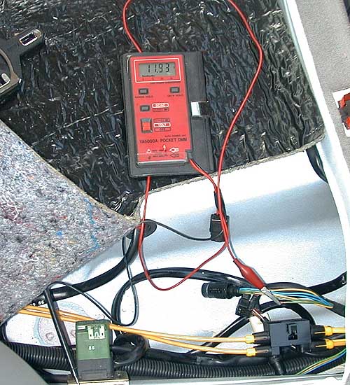
With the doors in the unlocked position, connect a voltmeter from the harness end of the green wire you cut to ground. We have used one of the screws connected to the relay on the left below as ground.
If you cut the correct wire your voltmeter will read approx 12 volts.
If you only get about 9 volts you cut the wrong wire. Use the supplied splice connector to reconnect this wire and cut the other green wire.
STEP-8
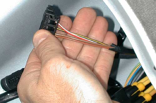
Trim back some of the sheathing on the rectangular connector to expose the wires.
STEP-9
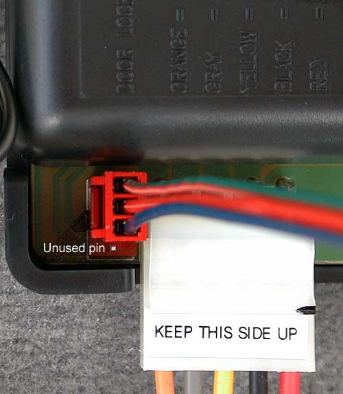
Connect the various parts as shown below.
Insulate the ends of the "unused" blue, purple and brown wires with electrical tape.
The "Extra wires" can be used as a source of wire.
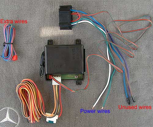
Close-up of connections...
STEP-10
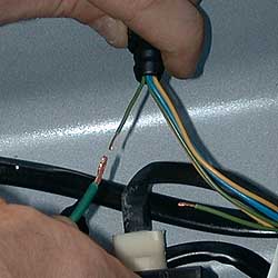
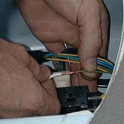
Using butt connectors...
Connect the green power wire to the cut green wire from the round connector.
Connect the white power wire to the cut green wire from the harness.
Step-11
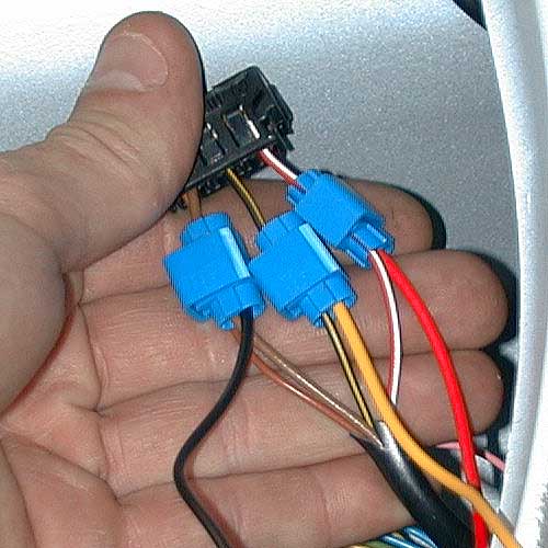
Find the black, yellow and red wires in the bundle of wires near the "Mercedes Star" in the photo from step-9 above. Using scotch locks, connect these wires to the wires on the rectangular connector:
- black connects to either of the brown wires
- yellow connects to the black/yellow
- red connects to the red/white
STEP-12
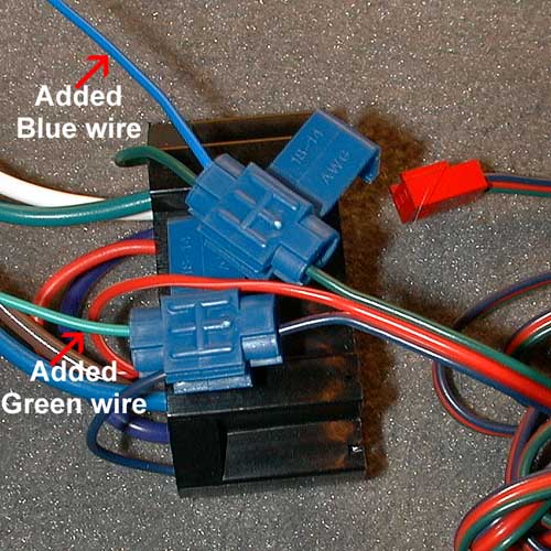
2 wires need to be added to the relay block. You can cut and use 2 of the "extra wires" shown in the picture from step-9. We simply used a 4.5 ft blue and green wire.
Find the green and blue wires that go from the relay block to the red connector.
Using the scotch locks, add the blue wire to the green wire and add the green wire to the blue wire.
Note- the scotch locks in the picture below have not been closed. You must close the scotch locks using pliers to insure a connection.
STEP-13
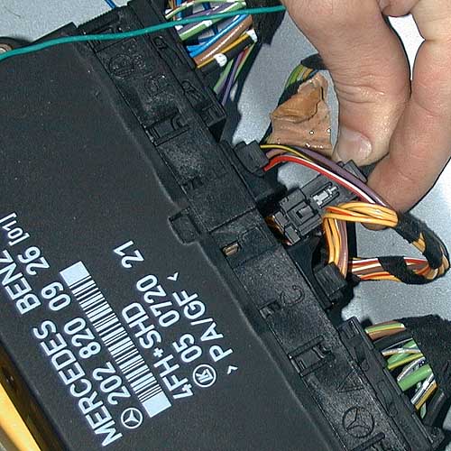
Unplug the "D" connector from the Convenience Control Module and trim back enough of the black sheathing to expose the wires for step-14.
STEP-14
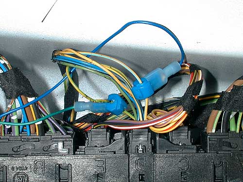
Find the green/yellow wire on the "D" connector and splice the green wire to it that was added in step-12 above.
Find the yellow/light blue wire on the "D" connector and splice the blue wire to it that was added in step-12 above.
STEP-15
Find antenna wire. This is the single black wire that is sticking out of the side of the REC-8 module. For best reception, the antenna wire should be fully extended across the car. Simply tape the end of it to the carpet pad to make sure it stays extended.
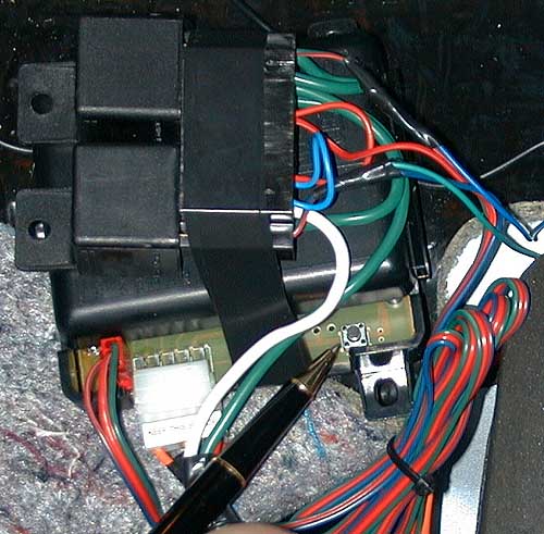
Install the 2 relays into the relay block and tape the relay block to the REC-8 module.
Find the "programming button" on the REC-8 module (shown by pen below). Go to page-16 of your REC-8 owner's manual. You will need to follow the instructions there to make any programming changes you would prefer.
STEP-16
Reassemble everything from steps 1 through 5.
- Benzmac
CategoryDiy